Case Study: Impact versus Impact – Comparison of different filter modes for vibration measurement
Root cause analysis, impact detection and verification for reciprocating machinery such as piston and hyper compressors are always challenging. When talking about condition monitoring of reciprocating machines, vibration signals are an integral element used for monitoring of different components, such as crosshead, valves, frame, etc.
Analysing vibration signals is a challenge for each monitoring system, and analysts needs tobe aware of the filter configuration to take the right conclusion for proper action. The goal is to minimize nuisance alarms and maximize the capability of early (automatic) failure detection.
Filtering a vibration signal helps to avoid noise, but on the other hand it should be set in the right way to indicate problems and not conceal them. For the right procedure, filtering, and protection limit adjustment always must be considered together. In the paper, signal analysis
considerations and their consequences for failure detection will be explained, such as filtering, analysing RMS vs. Zero-to-Peak, Good vs. Bad condition, etc ..
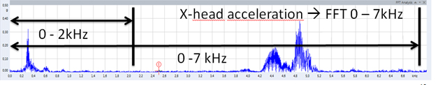
Figure 1: Crosshead guide acceleration data from 0-7 kHz during an event (in “g”).
The paper introduces the theoretical background proven by real-life case studies as an add-on the publication of Bob Eisenmann and Oliver Franz. lt is showing different failures on crossheads, piston/plunger, and valves.
History has shown that within the fleet of reciprocating compressors numerous catastrophic failures result in significant lasses. Although adequate machinery protection systems are available, they are not always in place or applied correctly to avoid catastrophic failures.
Numerous case studies with several different failure modes identify that appropriate frequency filter setting have major impact on the machinery protection system·s ability to function as needed when critical conditions arise.
Additionally, the application of RMS-based analysis instead of peak-analysis is also discussed. This article discusses the most important aspects to consider when implementing machinery protection systems using crosshead acceleration and frame velocity on reciprocating compressors – specifically:
■ Requirements and the Frequency Filter Setting Challenge
■ Signalanalysis consideration – Filter Setting / RMS / Peak
■ Crosshead acceleration – Why – Where applied – Effective analysis approach
■ Frame velocity – Why – Where applied – Effective analysis approach
■ Conclusion
Knowledge surrounding proper low pass filter settings for acquisition systems performing critical shutdown function is very limited and often misapplied. 2 kHz is used in several ISO vibration standards such as ISO 20816-83. This paper illustrates why the common practice of setting low pass signal filters at 2 kHz introduces risk that serious failure modes go undetected compromising plant safety, health, and the environment.
Which frequency range should be used for the low pass filter for crosshead guide acceleration to provide the earliest and best representation of the compressor health? Figure 1 is an example of crosshead guide acceleration data from 0-7 kHz during an event showing what data would be missed if only 0 – 2 kHz verse 0 – 7 kHz are used.
In the case studies investigated, we can conclude that frequency filter setting is vital in detecting failure modes such as wrist pin seizures, developing cracks in pistons and piston rods.
Signal Analysis Considerations
Modern machinery protection systems apply a fully continuous online RMS analysis of focus signals such as crosshead acceleration and velocity. This is a beneficial approach specifically on reciprocating compressors where an early indication of damaging impacts is of the essence and RMS values are best to describe the energy within a given signal as calculated by the equation in figure 2.
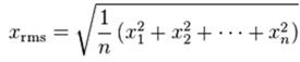
Figure 2: RMS value for an evaluation period represented by a number of “n” data samples is the square root of the arithmetic mean of the squares of the “n” values.
While the proper representation of contained energy is a positive factor, there is a risk that individual, high data samples get lost in the average.
This is specifically the case if the number of total samples “n” in the evaluation period is high e.g., when the Xrms equation above is evaluated over one entire revolution of the rotating machine or one second eventually containing hundreds or thousands individual data samples.
Furthermore, the reliable RMS computation and alarming in real time requires modern, redundant CPUs to handle this significant processor workload eventually occurring on multiple sensor channels in parallel.
Zero-to-Peak analysis
Some systems take a different path by employing Zero-to-Peak (Peak) or Crest Factor analysis instead of RMS, like mentioned in Appendix D of ISO 20816-83. This addresses the effect that RMS analyses may undervalue high individual samples when evaluation periods are relatively long (e.g., 1 compressor revolution or 0.2 sec @ 300 rpm) and compares maximum values detected in that period against a set of Alert and Shutdown limits.
Unfiltered peak analysis however leaves users vulnerable for nuisance alarms, e.g., caused by isolated, high frequency events, non-repetitive signal spikes and sensor glitches. In order to address these nuisance alarms some users apply a low pass filter (e.g., @ 2 kHz) so only the 0-2 kHz frequency content is analysed for its peak vibration content.
While the above strategy reduces nuisance alarms when using peak analyses, it also eliminates capability to detect many critical failure modes containing majority damaging energy in higher frequency ranges as will be discussed next.
Crosshead – Acceleration Sensors
Looking at the working principal of reciprocating compressors the crosshead clearly is a focal point. Here, the rotating movement of the crankshaft is transformed into a reciprocating (linear) movement of the piston rod. It is the central component where the major drive forces are transferred from the running gear to the crosshead and ultimately the piston rod assembly.
To contain these forces into the right direction, the crosshead travels within the crosshead guide. The crosshead guide is the most direct connection of the running gear to the frame/crosshead guide and therefore is the best position to install vibration sensors.
Therefore, API 6701 – (Annex P.4.3.4.4) recommends that crosshead accelerometers should be mounted in the vertical direction on the top or bottom of the crosshead guide as shown in Figure 3. API 6701 also stats that a monitoring system should be capable to monitor at least 2 kHz, with the add on “up to 7 kHz”, which is useful in many cases, like the ones demonstrated further down.
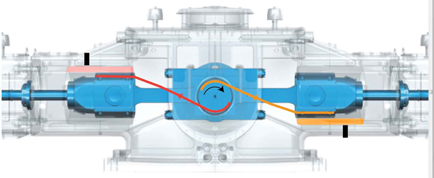
Figure 3: Proper placement of crosshead accelerometers – ideally these are installed vertically, external to the loaded crosshead shoe.
Frame – Velocity Sensors
The reciprocating compressor frame and crosshead guides are the stationary components anchored to the foundation to retain the compressor during operation. The frame/foundation is subjected to the normal unbalanced forces and moments from the reciprocating compressor inertial and gas loads as well as forces experienced during failure events.
Transducers placed on the corners of the frame in the horizontal and/or vertical direction are used to detect issues with the support structure/foundation. Transducers mounted in the horizontal direction directly opposing each throw are used to detect impacts and mechanical issues.
API 6182 also identifies high frame vibration as alarm and shutdown parameter but does not fully define what should be provided. API 6701 clause P4.3.4.2 and P4.3.4.3 identify the recommendations of frame monitoring and running gear monitoring respectively.
In many cases the acceleration sensor on the crosshead detects machine issues earlier like a frame velocity sensor, therefore following chapters focus on acceleration monitoring and filtering. Anyhow the velocity sensor is important as an additional information about low frequency vibrations at the machine and notable in this paper.
Practical examples and case study material for acceleration signals
Seized Wrist Pin
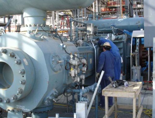
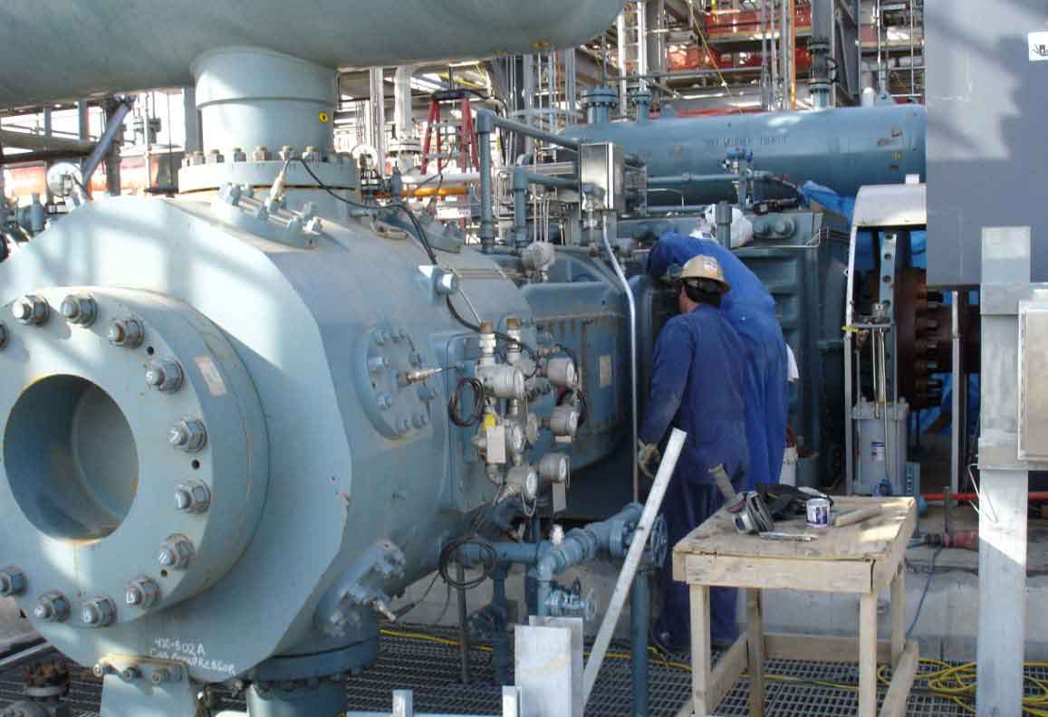
During the commissioning and start-up of a new API 6182 compressor in H2 service the machine was suddenly tripped by the machinery protection system. A first data review revealed that crosshead acceleration amplitudes reached the default protective limits having saved the asset from consequential damage or loss of containment. During a detailed analysis of the high-resolution data available this first case study is an excellent example illustrating the importance of high frequency (0-7 kHz) data for effective machinery protection with crosshead acceleration sensors.
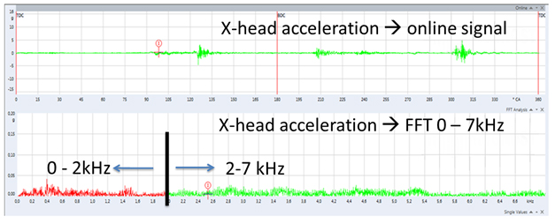
Figure 4: Good condition signal – Top: time-waveform, online signal (0-7kHz) Bottom: Spectrum 0-7kHz
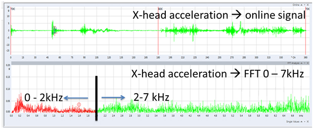
Figure 5: Bad condition signal – Top: time-waveform, online signal (0-7kHz) Bottom: Spectrum 0-7kHz
The wrist pin seizures detected did not involve true mechanical impacts typical of loose components (showing lower frequency content primarily below 2 kHz). Comparison of Figure 4 “Good Condition Signal” to Figure 5 “Bad Condition Signal” shows most of the failure related energy as well as relative signal change has higher frequency content above 2 kHz. To initiate the trip function prior to a catastrophic failure and potential loss of containment the full 0-7 kHz frequency spectrum suggested by API 6701 must be monitored.
Failed Piston Rod
A broken piston rod is potentially one of the worst-case failure scenarios for a reciprocating compressor. Detecting this critical failure mode timely and accurately is very important.
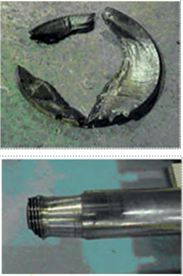
Figure 6: Fragments of the piston rod thread region. Top view of the failed piston rod thread region.
This end user suddenly experienced increased crosshead acceleration impacting which ultimately lead into an automatic shutdown of his protection system. The maintenance team found the piston rod failed within the thread region connecting the piston rod and crosshead as shown in Figure 6. This second case offers additional insights regarding the importance of proper frequency filter settings.
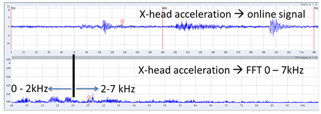
Figure 7: Good condition signal – Top: time-waveform, online signal (0-7kHz) Bottom: Spectrum 0-7kHz
The online vibration and spectral data shown in Figure 7 represents a very characteristic crosshead acceleration signal of a reciprocating compressor with some limited vibration around the rod load reversal points and little to no energy content visible in the higher frequency section within the FFT spectrum.Please note that those data plots following now titled with “bad condition” represent data from the revolution when the machine was automatically tripped by the machinery protection system. Before that the vibrations increased over time.
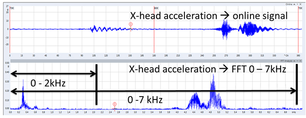
Figure 8: Bad condition signal – Top: time-waveform, online signal (0-7kHz) Bottom: Spectrum 0-7kHz
As shown in Figure 8 a true amount of energy was found between 4 – 5 kHz which made us apply different frequency filters to determine how important the appropriate filter setting really is to detect a case like this effectively.
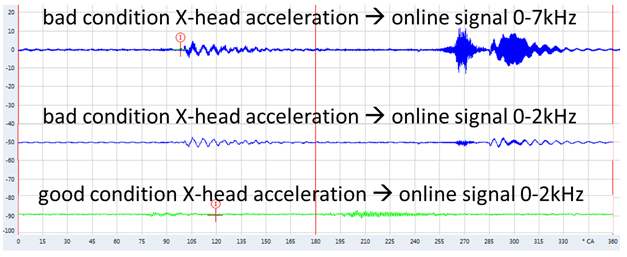
Figure 9: 360°crank angle online signals applying different filters 0-2 kHz and 0-7 kHz under good and bad condition.
When comparing the “good” (Figure 9 bottom) vs “bad” (Figure 9 middle) 0-2 kHz the measured online signals differ not much, and a machinery protection system would have missed this critical failure if the signal does not exceed and alarm or trip level.
The failure however becomes obvious inside the online data set “bad” at 0-7 kHz (Figure 9 top) which shows a significantly different picture and lot of energy around 270° crank angle (CA) and 300°CA not visible in the “bad” 0-2 kHz filtered online data (Figure 9 center).
This failing piston rod was automatically detected using a 36 segmented RMS analysis of the crosshead acceleration signal using the full signal bandwidth (in this case 0-10 kHz).
It subdivides each revolution in smaller segments (e.g., 10-degree crank-angle wide increments) each with a dedicated protection limit. Areas with naturally higher vibration levels within each revolution (e.g., rod load reversal points) get the appropriate focus and at the same time solid ten-degree averages eliminate isolated spikes in each segment.
While we have discussed the basics of RMS vs. Peak analysis in a previous chapter, a 36 segmented RMS vibration analysis combines the best of both approaches.
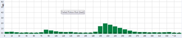
Figure 10: Good Condition 0 – 7 kHz RMS 36 segmented analysis
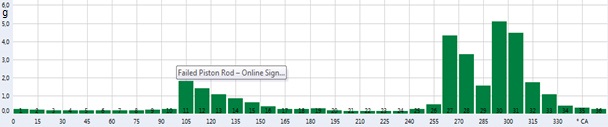
Figure 11: Bad Condition 0 – 7 kHz RMS 36 segmented analysis
Reviewing data plots of Figure 10 and Figure 11 above the effectiveness of this approach becomes apparent. Segments 27-33 (270 – 330°CA) show a massive increase in amplitude for 0-7 kHz – some by more than factor 10.
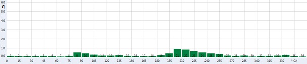
Figure 12: Good Condition 0 – 2 kHz RMS 36 segmented analysis
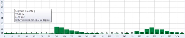
Figure 13: Bad Condition 0 – 2 kHz RMS 36 segmented analysis
However, even when applying a sophisticated analysis like the 36 segmented RMS analysis it should include higher frequency data. Figures 12 and 13 represent data employing a 2 kHz low pass filter.
Between good (Figure 12) and bad condition (Figure 13), a much lower relative change in amplitude is found – and while under good condition worst acting segments show around 1g – values only increased to 1.3g as the piston rod cracked due to the fact that the majority of failure related energy is filtered out and not part of the evaluation.
Conclusion and Recommendations
The latest additions to API 6701 provide valuable information for machinery protection on reciprocating compressors. Specifically, the addition of crosshead acceleration is essential, and users should take care employing this powerful protection parameter at its best capacity.
As we have demonstrated certain failure modes show majority of energy at higher frequencies (e.g., 4 – 7 kHz). This is why we suggest following API 6701 and employ full signal bandwidth 0 – 7 kHz ideally combined with a segmented RMS analysis – this way repetitive impacts are not missed at critical stage and RMS based segments represent a solid (e.g., 10°crank angle) weighted average, and single isolated signal spikes do not lead to nuisance alarms, which may occur using unfiltered peak analysis.
Modern machinery protection systems employing crosshead acceleration sensors in the first place and frame velocity as an additional layer of protection per recommendations provided within this paper will help detecting many critical failure modes in an early stage preventing catastrophic failures.