Case Study: Early Failure Detection and Shutdown of a Compressor Due to Crosshead Fracture
Timely Shutdown Ensured with Modern Monitoring and Machine Protction Systems
A PROGNOST Systems customer in Germany operates four, four-cylinder reciprocating compressors at a natural gas production facility in Northern Germany. This case study describes the detection of critical damage in the crosshead with a subsequent safety shutdown to avoid consequential damage.
Different parameters such as crosshead slide vibration and piston rod position are monitored for the detection of the failure and shutdown of the compressor. This article describes the development of the failure and its detection, as well as the root cause of the failure in the demanding H2S environment.

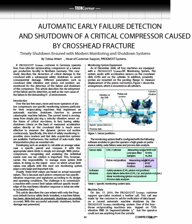
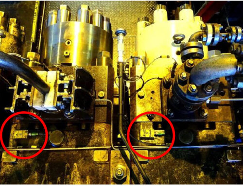
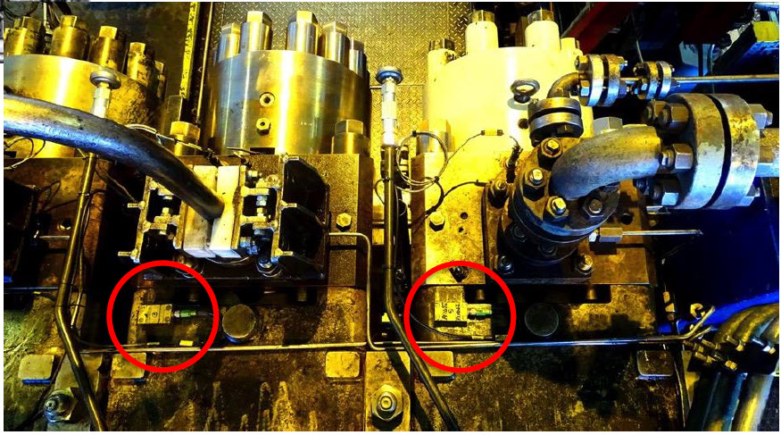
Figure 1. Sensor positions
Introduction
Over the last few years, more and more operators of piston compressors use specific monitoring systems particular for their reciprocating machines that implement an automatic machine shutdown function to prevent catastrophic machine failures. The current trend is moving away from simply placing a velocity vibration sensor on the frame of critical machines.
In fact, having safety shutdown criteria based on measured acceleration values directly at the crosshead slide is much more effective to measure the dynamic piston rod motion continuously. Specifically, this kind of safety monitoring is possible, since modern and fast data acquisition systems are available. Furthermore, the method of automatic data interpretation plays an essential role.
Developing such an analysis to calculate an average value over a specific period and compare it with the appropriate alarm limits is simply not enough. With piston compressors, recognizing and analyzing the individual events over one revolution is important. This, however, carries the responsibility to manage more system limit values. In doing so, the experience on which actual limit-values one adjusts with this modern monitoring system plays a very large and important role.
Usually, these limit values are based on actual measured values. This is because each piston compressor has specific vibration responses and signatures according to its design and operating conditions. The challenge is to commission a machine with correct limit values without specific knowledge of the machinery vibration response or what we refer to as baseline data.
This article describes the case where with only the PROGNOST Systems default factory safety limits installed, a machine failure has been detected, and an automatic shutdown successfully occurred. With this successful automatic shutdown, further damage was prevented.

Table 1. Specific monitoring system data
Monitoring System Equipment
As of December 2006, all four machines are equipped with a PROGNOST-NT Monitoring System. The system works with acceleration sensors on the crosshead slide (CHS) and on the cylinder. In addition, proximity probes are mounted on the packing flange to measure displacement of the piston rod motion. Figure 1 shows the arrangement, which is mounted on all cylinders.
Machine Data
On Jan. 17, 2010, the PROGNOST Systems customer support specialist received a hotline call. This call was made by the customer to ask for verification of data based on a current automatic machine shutdown by the PROGNOST monitoring system. One of the four-throw reciprocating machines was tripped on “CHS vibration RMS 36 Segment/cylinder 2,” but the operator could not see anything from the outside of the machine. Note: This call was based on the customer’s service agreement procedure.
The machine in question is a four-throw, single-stage, double-acting, natural gas transportation unit (model-year 2005) with bore and stroke of 6.9 and 9.65 in. (175 and 245 mm), respectively. Rotation speed range is between 380 and 740 rpm. Power rating is 2280 hp (1700 kW). It is equipped with a stepless speed and valve unloader (25-50-75-100%). Suction and discharge pressure is 435 and 1160 psi (30 and 80 bar), respectively, while suction and discharge temperatures are 59° and 302°F (15° and 150°C), respectively.
Safety Limit Configuration
The proven strategy for vibration analysis is the so-called segmented vibration analysis based on 36 segments. Each 10° crank angle (CA) represents one segment per revolution on which the RMS vibration value is calculated.
For each segment there is an individual limit that can be set independently from each other to avoid false alarms given by higher values caused, for example, by high discharge valve impacts or higher vibration levels at the rod load reversal points.
As well, the system checks the peak-to-peak value of the piston rod position signal based on eight segments per revolution (Table 2). In addition, the system counts the quantity of segments during a specific number of rotations and in which and how many segments a limit is violated.

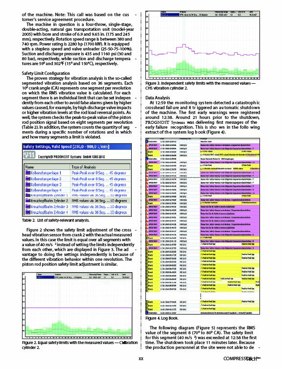
Table 2. List of safety-relevant analysis
Figure 2 shows the safety limit adjustment of the crosshead vibration sensor from crank 2 with the actual measured values. In this case the limit is equal over all segments with a value of 40 m/s2 instead of setting the limits independently from each other, which are displayed in Figure 3. The advantage to doing the settings independently is because of the different vibration behavior within one revolution. The piston rod position safety limit adjustment is similar.
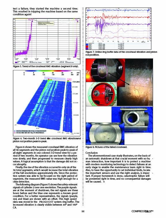
DataDaData Analysis
At 12:59 the monitoring system detected a catastrophic crosshead failure and it triggered an automatic shutdown of the machine. The first early warnings were registered around 12:38. Around 21 hours prior to the shutdown, PROGNOST Systems was delivering first messages of the early failure recognition. This is shown in the following extract of the system log book (Figure 4).

Figure 4. Log Book
The following diagram (Figure 5) represents the RMS value of the segment 8 (70° to 80° CA). The safety limit for this segment (40 m/s2) was exceeded at 12:38 the first time. The shutdown took place 11 minutes later. Because the production personnel at the site were not able to detect a failure, they started the machine a second time. This resulted in tripping the machine based on the same condition again.

Figure 5. Trend of the crosshead RMS vibration (segment 8 only)
Figure 6 shows the measured crosshead RMS vibration of all 36 segments and the piston rod position peak-to-peak of all eight segments in one colored 3-D trend view for a period of two months. An operator can see how the vibration rose slowly, and then progressed to measure clearly high values. A logical assumption is that the damage did not occur abruptly.
Finally, the rise of the vibration occurred in only six of the 36 total segments, which would increase the total vibration of the full revolutions approximately 6%. Since the protection system was able to be focused on the right period of segments, the measured RMS value was high enough for a clear detection.
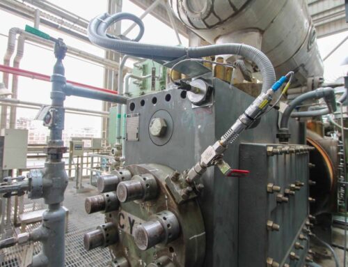
The following diagram (Figure 7) shows the safety-relevant signals of cylinder 2 over one revolution. The purple signals are at the moment of shutdown; the red signals are three hours before and the blue one represents a known good condition. For a better representation, the signals (purple, red, and blue) are shown with an offset. This high-speed data was stored in the PROGNOST system ring buffer. The increased vibration is clearly visible between 40° and 100° CA.

Figure 6. Two-month 3-D trend of the crosshead RMS vibration and piston rod position peak-to-peak

Figure 7. Online ring buffer data of the crosshead vibration and piston rod postition
Conclusion
The case study illustrates, on the basis of an automatic shutdown at that crucial moment with no human interaction, how important it is to protect a machine with modern monitoring technology to detect failures at an early stage to enable the maintenance team right in time. Also, to have the opportunity to set individual limits, locate the important sensors and use the right analysis, is important. If proper homework is done, catastrophic failure will be prevented right in time, and no consequential damages will be caused.

If you want to know more about our solutions for effective vibration monitoring for reciprocating compressors: Just contact us via the contact form. We would be happy to hear from you!
