PROGNOST®-NT Helps to Improve a Refinery’s Machine Protection
Introduction
Compressor crosshead fractures are costly damages, leading to unplanned outage of the system and loss of production. PROGNOST Systems claims that the development of fractures in the motion work, especially on the crosshead, can be detected by using the segmented Peak-to-Peak piston rod position analysis.
The company also recommends this as a mandatory parameter and for safety interlock. This claim was proven to be true by a complete fracture of a crosshead which could have been avoided if the automatic interlock had been activated by the operator. The experience of this case also motivated the operator to improve his site shutdown philosophy.
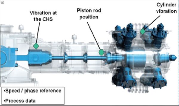
Figure 1. Sensor positions
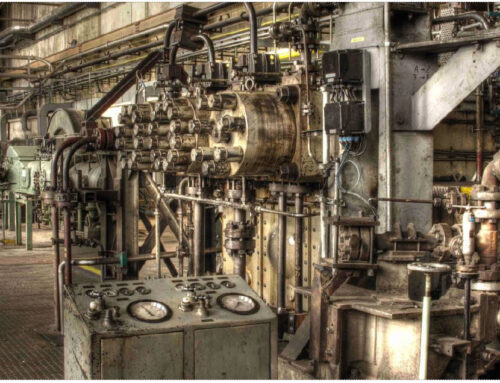
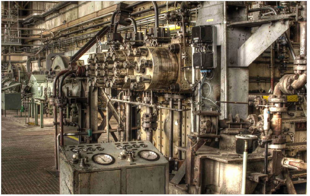
The installation
In place at refinery in USA, was a Nuovo Pignone reciprocating compressor which was taken into operation in 2004. Since the initial start-up, the PROGNOST®-NT system had been used to detect common faults such as valves, riders, rings and others.
The overall compressor reliability had been very good. No failures in the motion works components occurred; no Prognost safety alert or alarm limit of CHS vibration (active) or Rod Position (inactive) had been reached.
Failure History
In 2011, the compressor had the first major overhaul in seven years due to a knock. Several parts as 1st stage connecting rod, bearings, crosshead pin and the main bearing liners were replaced. The crosshead failure described here occurred eleven months after this service works had been carried out by a non OEM-contractor.
Development of the crosshead fracture
At the time the event started, the compressor was running steady at a normal load of 75%.
- 29 hours prior the break, the PROGNOST®-NT system issued the first diagnostic message. It reported the following damage class: “Crosshead / Piston Rod / Piston Stage 1 with a correlation of 100%”
- During the last minutes, there was a steady increase from the first diagnostic message (pre-alarms) to alarm (shutdown). In addition, the vibration safety limits of the crosshead slide were violated in several segments.
- 60 seconds before the crosshead failed, the 1st stage piston rod position reached the trip levels.
- After the crosshead parted and the vibration alert conditions on both crossheads were reached, the automatic shutdown was initiated on the crosshead slide vibration.
- Due to the fact that the compressor previously had issues with a low lube oil pressure, the operators interpreted the trip as being related to these problems. They checked the oil system, found it to be good and re-started the compressor 32 minutes after the safety shutdown.
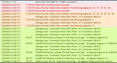
Figure 1: The logbook of the last 30 minutes before the fracture illustrates the development from the first diagnostic messages (green) to pre-alarm (orange) to the main alarm (red).
The data analyses showed that the crosshead slide vibration and the rod position were both giving a normal online signature seven days prior to the failure. The crosshead vibration safety limits were set between 2.0 and 2.3 g.
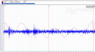
Figure 2: The normal online signature of the compressor seven days prior to the event
(CHS RMS vibration = blue; Piston rod position = red curve)
60 minutes before the event, the crosshead vibration and the rod position was well below the safety limits. Two minutes prior to the fracture, the crack development was visible in the CHS vibration RMS analysis in four segments. For the safety shutdown, violations in six segments were needed.
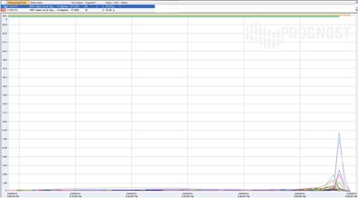
Figure 3: The crack development is visible in the RMS short term trend two minutes prior to the fracture, but only in 4 segments (33, 34, 35, 36). Six were needed for the trip.
Compared to the crosshead, the rod position increased ten minutes earlier, averaging 51.23 mils 60 seconds prior to the trip. 15 seconds before the trip, the rod position reached 71.2 mils, exceeding 90 mils during the last three revolutions.
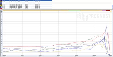
Figure 4: The curve of the dynamic piston rod position shows a rapid increase within the last revolutions. Each line (blue, green, red etc.) represent one of the eight segments the 360° crank-angle are divided into.
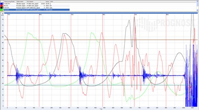
Figure 5: The green curve indicates the loss of pressure within the compressor caused by the separation of the crosshead.
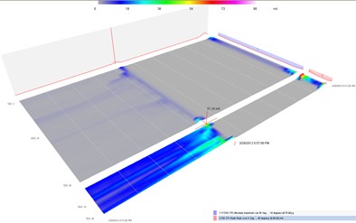
Figure 6: 3D Waterfall trend of one hour. The blue surface represents the RMS of crosshead vibration over 360° crank-angle. Reaction after the operator overruled the trip released by the Prognost system.
Sequence of events
| Time | Event | Cause |
| Immediate shutdown by PROGNOST®-NT | ||
| +32 min. | Restart by operators on deck | |
| 17:55 hrs. (05:55pm) | Compressor tripped | RMS Crosshead vibration Stage 1 and 2 |
| Pressure curves show crosshead separation | ||
| Crosshead parted | ||
| Last 3 revs. | Rod position exceeded 90 mils | |
| -15 sec. | Rod position 71.2 mils | |
| -60 sec. | PROGNOST Main alarm (Automatic trip deactivated by customer)Pre Alarm |
1st stage piston rod position (51.24 mils)
1st stage CHS RMS vibration |
| -120 sec. | Crack development visible | CHS RMS vibration (4 of 6 segments) |
| -10 min. | Rod position ~ 22 mils | |
| -29 hrs. | Diagnostic message | “Crosshead, Stage 1, 100%” |
| -7 days | Crosshead RMS ~ 0.4 g, Rod Position ~ 18 mils | |
| SAT | Crosshead RMS Safety limits settings between 2.0 and 2.3 g | |
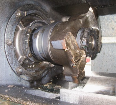
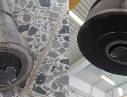
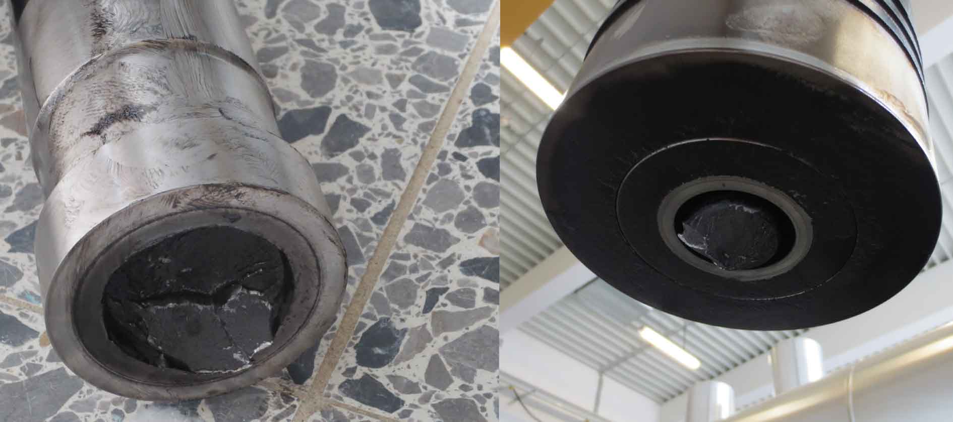
Fig 7: Real-life proof of data analyses: the broken crosshead.
Taken together, all data fully illustrated the reaction of the system shortly before the separation of the crosshead as well as what happened when the operator team overruled the shutdown initiated by the PROGNOST®-NT system.
The shutdown settings from the SAT protocol (Site Acceptance Test) showed the detailed safety limits and criteria for the activation of pre-alarm and main alarm. It also proved the disabling of analyses by resetting the safety alarm if the machine stops.
Fracture experience for a new safety shutwon philosophy
After the complete fracture of the crosshead, the data analyses led to several conclusions on the operator’s side. First of all, the Prognost monitoring showed that the developments of this type of crosshead fracture cannot be detected at an early enough stage by using the crosshead vibration alone. The use of piston rod position measurements has proven to be a reliable factor for safety protection.
As a result, the monitoring of piston rod measurements is now part of the site shutdown philosophy on machines equipped with Prognost at the refinery. In addition, operators are no longer permitted to re-start a compressor tripped by a Prognost system. Thus, the PROGNOST®-NT system now helps to avoid costly damages to Rotating Equipment, lowering outage and securing productivity at the refinery.
Summary:
A refinery in Texas equipped two H₂ compressors with the PROGNOST®-NT monitoring system to support predictive maintenance and detect early signs of wear.
Continuous monitoring revealed rapid rider band wear caused by residual abrasive contaminants, with distinct wear patterns between the two compressors.
Thanks to accurate wear trend analysis, the Reliability Team was able to schedule timely maintenance and avoid costly damage.
The success of this approach built trust in the system, allowing the team to rely on data-driven decisions for future outages.

